


321.A timber beam of rectangular section 100 mm x 50 mm is simply supported at the ends, has a 30 mm x 10 mm steel strip securely fixed to the top surface as shown in Fig

30 mm
322. The 'Euler' load for a column is 1000 kN and crushing load is 1500 kN. The
'Rankine' load is equal to
600 kN
323. Fig. shows a retaining wall of base width B₁ and height H₁. The sp. gravity of the material of construction is S. Further AB = BC = CD = B₁/3

When the depth of storage increases from 0 to Hi, the resultant force will move
from B to C
324. A column section as indicated in Fig is loaded with a concentrated load at
a point 'P' so as to produce maximum bending stress due to eccentricities about
xx axis and yy axis as 5 t/m² and 8 t/m² respectively.

If the direct stress due to loading is 15 t/m² (compressive), then the intensity of
resultant stress at the corner 'B' of the column section is
12 t/m² (compressive)
325.Two similar round bars A and B are each 30 cm long as shown in Fig.

The ratio of the energies stored by the bars A and B,
3/2
326.

A. Maximum principal stress - 18.0
B. Minimum principal stress - -8.0
C. Maximum shear stress - 13.0
D. Normal stress on the plane of maximum shear stress - 5.0
327
A. Impulse - Time effect of a force B. Torsion - Modulus of rigidity C. Plane of loading - Shear centre D. Instantaneous centre of rotation - Plane motion
328. A truss ABC, carries two horizontal and two vertical loads, as shown in Fig

The horizontal and vertical components of the reaction at A will be
329.In the cantilever truss shown in Fig. , the reaction at A is

30 t
330.

331.The deflection at the free end of a cantilever subjected to a couple M at its
free end and having a uniform flexural rigidity EI throughout its length 'L' is
equal to
ML²/2EI
332. In Fig., the maximum bending moment at the fixed end of the cantilever caused by the UDL is M 4% of M

333. The shear force diagram for a simply
supported beam of span T is given in Fig

The maximum bending moment is
Wl₁
334.
List 1 - List2
A. Clapeyron - Theorem of three moments B. Hardycross - Moment distribution method C. Lame - Thick cylinders D. Euler - Method for determining crippling load on a column
335. A propped cantilever of span T carries a uniformly distributed load of 'w' per unit run over its entire span. The value of prop reaction to keep the beam horizontal is (3/8)wl
336. ABCD is a beam of length 5/ which is supported at B and C (having supported
length BC = 1) and having two equal overhangs AB and CD of length 21 each. It carries a u.d.l. of intensity p per unit length throughout the beam as shown in
Fig.
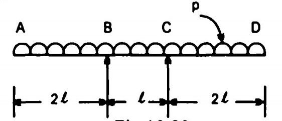
The points of contraflexure will occur
nowhere in the beam
337.

The structure shown in Fig. is stable if
x = √2 y
338. Two simply supported beams B₁ and B₂ have spans l and 2l respectively. Beam B₁ has a cross section of 1 x 1 units and beam B₂ has a cross section of 2 x 2 units. These beams are subjected to concentrated load W each at the centre of their spans. The ratio of the maximum flexural stress in these beams is 4
339. In a particular material, if the modulus of rigidity is equal to the bulk modulus, then the Poisson's ratio will be 1/8
340. Consider the following statements : When two planes at right angles are
subjected to direct stresses, the Y axis which denotes shear stress, will pass
through the centre of the Mohr's circle when the direct stresses are
1. equal in magnitude
2. of opposite signs.
Comments