341.
1.The condition that Ld < (M₁/V + L0) need not be checked for negative
reinforcement
2. At least one-third of the total negative reinforcement provided must extend beyond the point of inflection for a distance not less than d, or 12 Φ or
clear span whichever is large
342. In a RCC beam of breadth b and overall depth D exceeding 750 mm, side face
reinforcement required and the allowable area of maximum tension reinforcement shall be respectively 0.1 % and 0.04 bD
343. In limit state design of reinforced concrete, deflection is computed by using
short and long-term values of Young's modulus
344. As per IS:456-1978 the vertical deflection limit for beams may generally be assumed to be satisfied provided that the ratio of span to effective depth of a continuous beam of span up to 10 m is not to be grater than 26
345. Negative moment in reinforced concrete beams at the location of supports is
generally much higher than the positive span moment. This is primarily due to
curvature at the supports being very high
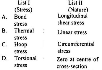
346.

347. In the conventional prestressing, the diagonal tension in concrete Decreases
348. Beam sections of reinforced concrete designed in accordance with ultimate
strength or limit state design approach, as compared to section designed by working stress method for the same conditions of load and span, and the same width, usually have smaller depth and more reinforcement
349. A doubly reinforced beam is considered less economical than a singly reinforced beam because compressive steel is under-stressed
350. The ultimate strength of the steel used for prestressing is nearly 1500 N/mm²
351. Assertion A: In the working stress method, the stress in compression steel is taken as 1.5 x modular ratio x stress in surrounding concrete.
Reason R: The modulus of elasticity of concrete in compression is only two-thirds
of that intension.
352. Assertion A: Losses in prestress of pretensioned beams are more than the
losses in post-tensioned beams.
Reason R: This is partially due to the effect of elastic shortening.
353. Assertion A: The development length for HYSD Fe 415 bars is less than that for
mild steel plain bars.
Reason R:The permissible bond stress for HYSD Fe 415 bars is more than that for
mild steel plain bars
354. Assertion A: Bridges designed for class AA loading should be checked for class-A Loading also.
Reason R: Under certain conditions, heavier stresses may be obtained for class
A loading.


Comments